 |
| March 23, 2021 | Volume 17 Issue 12 |
Designfax weekly eMagazine

Archives
Partners
Manufacturing Center
Product Spotlight
Modern Applications News
Metalworking Ideas For
Today's Job Shops
Tooling and Production
Strategies for large
metalworking plants
An in-depth look into hardware and software solutions for dynamic automotive EV testing
Topics in this article include a review of the drive and software solutions being applied to automotive test stands to address the needs of electric vehicles, including battery, e-powertrain, and motor performance.
By James Ellis, Motion Control Business Development Manager, Siemens Industry, Inc.
The shift to eMobility in the automotive industry has caused a number of changes to the test methodologies being used, with a heightened attention to the details of energy efficiency and solutions for providing clean, manageable, and predictable DC voltage.

In the macro view of the end-of-line test stand development for the emerging electric vehicle industry sector, we look to four key areas, namely, the dynamometer drive system, DC supply, engineering challenges, and overall machine safety. The core of the dyno drive system centers around a variable frequency drive paired with a high-performance drive motor. Secondly, the test stand requires a dynamic, configurable DC power supply to act as a battery simulation. Thirdly, using a single engineering platform, all the aspects of the PLC, HMI, Motion, Safety, and even Security factors come together for project planning, machine commissioning, and system programming. Finally, the fourth concern of overall machine safety will look to integrate safety concepts over a network without the need for additional, external hardware.
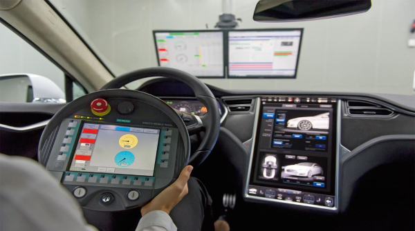
In an example test stand application for the electric vehicle powertrain systems, we are confronted with the need to test a hybrid transmission, electric transmission, battery or fuel cell, and motor, as well as differential gearing and transfer case. For roller rig and chassis dynamometers in the test lab environment, we have the new challenges in NVH and performance presented by an electric or hybrid powertrain. Conventional cold and hot engine test stands continue to be used, as do brake, drive shaft, component, and fatigue test stations plus balancing, tire, and steering test systems for component validation and evaluation.
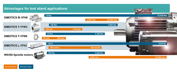
Various component testing requires a wide range of motor solutions as illustrated here.
The motors used for these new test stand development projects can include a range of high- performance drive motors for higher speed ranges, often up to 40,000 rpm, plus a variety of torque motors for evaluations at low speeds and linear motors for vibration testing on components that offer advantages, compared to often fluid-laden hydraulic methods. When these linear motors are configured in parallel or in a series, the force can be almost limitless, while achieving extreme dynamic accelerations and velocities. Such motors also offer substantial energy efficiencies compared to conventional fluid power systems.
Lastly, a conventional internal combustion engine runs red lines at 8,000 to 9,000 rpm, while the electric vehicle powertrain is typically running with much smaller gear ratios, so the gears and drive shafts are running at much higher speeds. This condition requires very heavy-duty spindle motors, which often run in a range of >40,000 rpm.
Once the motors are determined, the mating drive design can be addressed. Often, a very wide range of power ratings is demanded, from 0.12 kW to 1 MW with clean, efficient energy regeneration capability. Likewise, a higher degree of drive dynamics with corresponding motor speed/torque control features is required, as is a very high degree of scalability and flexibility in the design. Lastly, with the need to capture and transmit substantial amounts of data, multiple communication options in Profinet, Ethernet IP, and EtherCAT protocols are possible. Test stand developers require drives that can be engineered, parameterized, and commissioned with standard software and protocols to minimize build times, simplify end-user startup, and reduce time to market.
The best drives systems today are offering current controllers clock cycles capable of reaching 31.25 microseconds and pulse frequencies up to 32 kHz for superior torque, force, and speed control.
Safety concerns in new test stand development projects benefit from the corresponding and ongoing improvements in drive technology seen on gantries, a myriad of other materials handling applications, machine tools, and robotics. All have the common goal of protecting people and equipment alike. Drive-integrated safety functions must ensure a safe state in the event of an emergency stop. Available safety functions that should be considered include:
- Safe Torque Off
- Safe Stop
- Safe Brake Control
- Safe Limited Speed
- Safe Direction
- Safe Speed Monitor
- Safe Operating Stop
- Safe Stop 2
- Safe Brake Test
- Safe Limited Position
- Safe Position
Another emerging solution in drive design is cogging torque compensation for torque or linear motors, which offsets the magnet's tendency to follow the next coil in very low speed applications. The drive actually learns the phase sequencing and identifies the onset of cogging. This feature permits higher performance and optimal test results at a wider range of speeds. The drive can provide a constant torque at lower speeds plus the reduction of speed ripple in synchronous or asynchronous motors. Through a pre-controller in the drive, adjustable current is provided to eliminate the cogging.
A set-point generator, integrated in today's advanced drives, consists of three signal generators, namely sine-wave, saw tooth, and square-wave, which pulse the speed or torque based on a defined wave form. Inputting of the amplitude, frequency, and any offsets gives this drive function the ability to have very high resolution, even at very high speeds. Applications for this feature typically include balancing, tire, and wheel tests.
A further development in dynamic speed and torque simulation has emerged. This can generate a complex, pre-defined wave form and pulse the speed or torque set-points with resolution up to 10,000 interpolation points per cycle. Duplication of pre-defined wave forms improves outcomes of test procedures for various engine components, transmission, and drive lines. This new function can replicate realistic testing conditions with excellent torque precision and faster set-point function.
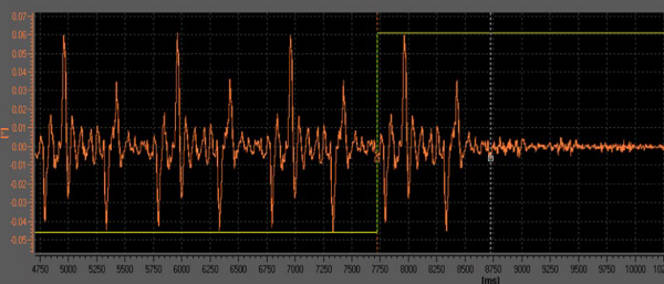
Speed error compensation shown here. When the learning and error compensation technology is activated, speed ripple is nearly eliminated.
Learning error compensation allows the testing procedure to mute disturbances within the part. Usually learned after four to six cycles, this automatic disturbance compensation functions in two modes: learn and capture, as well as continuous learn and compensate. Optimal bad engine recognition is the chief benefit here, as the drive function is a fast learner, especially useful on new engine and driveline tests. The function is available on the fly, so the control of disturbances can be run to monitor a consistent factor or disabled for other aspects of the test.
As electric motors have much higher rotation speed, often in the 20,000- to 40,000-rpm range, we have new challenges of achieving much higher pulse frequencies in the drive system. As these higher frequencies occur, the amount of current produced by the drive system is de-rated. This might normally favor large-capacity drives, but through a servo coupling function now available, multiple motor modules of lower individual amperage can be used without de-rating current at the higher pulse frequencies. This function also eliminates encoder splitters, as the speed controller with the encoder connection is positioned only on the master axis.
These higher level drive systems require correspondingly higher performing communications systems for data logging and external control. An isochronous Profinet system for cycle times up to 250 microseconds can achieve deterministic behavior without data collisions or jitter. Using ring topology for the higher level equipment, the benefits to the end user of this software include reduction of interface converters, no EMC influences, simple integration, higher performance due to more rapid memory access, and more consistent process data.
Another possibility offered today is an EtherCAT interface that utilizes the CANopen over EtherCAT drive profile. It features an integrated web server function accessible through onboard Profinet interface, so different motion control modes of position and speed are possible. A two-port switch supports daisy-chain topologies. The user benefits here include easy migration from CANbus to EtherCAT, user-defined web page flexibility, and easy wiring for synchronous operation on multiple axes applications.
We now turn to more specifics of dynamic test stand application developments required for eMobility.
With the emergence of electric vehicles, there is a requirement for a much higher DC power source on dynamic test systems.
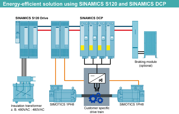
Testing of electric drive units (EDU) requires a configurable, dynamic DC power source that acts as the battery emulator. Energizing the EDU with proper voltage, 0 to 1,000 VDC powers the vehicle inverter and motor that turns the test article's drive line. This provides mechanical power to the adjoining motors, which convert that mechanical energy into electric power and regenerate to the DC bus. Note the absence of filtering hardware, the result of a true DC-DC converter.
In this next example, a battery test is performed by the hardware shown. Testing from 72 VDC to 1,030 VDC and 1,200 A is possible with clean energy regeneration satisfying IEE519 standards.
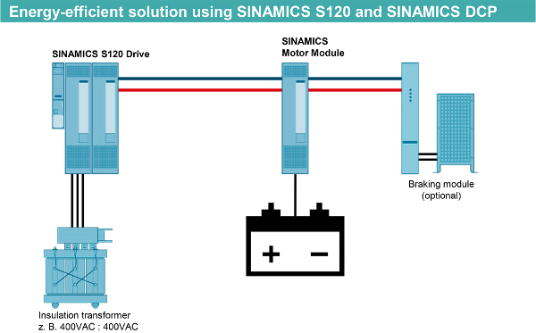
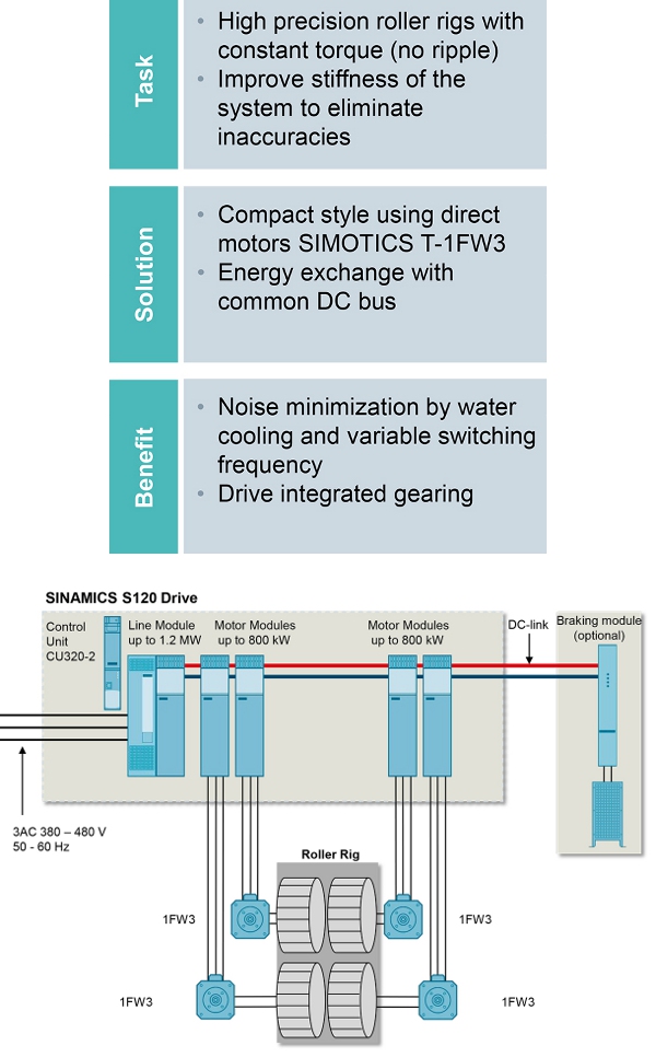
A more traditional roller rig uses regen energy provided by the shaft motors running on the wheels of the vehicle. A constant torque with no ripple improves the stiffness of the system to eliminate inaccuracies. The energy exchange is via a common DC bus, and noise is minimized by variable switching frequency.
Various other end-of-line, non-destructive testing and process-monitoring systems are rapidly emerging for the testing of electric motors, assemblies based on fault identification, resonance tests, breakage, and possible crack-detection monitoring.
Interested in learning more? You can contact the author at james.ellis@siemens.com.
Learn more about eMobility offerings from Siemens Industry here.
Published March 2021
*NOTE: Our feedback form isn't working right now. Please send article feedback to mfoley@nelsonpub.com. Thanks!
Rate this article
View our terms of use and privacy policy